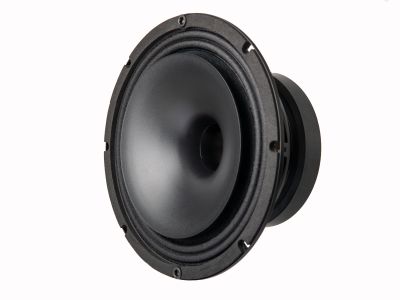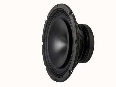

Coax
Coaxial
6"
CX6F140F
Code: CX6F140FX8X8-361C
Coaxial:LF-6"/Ferrite/Paper/100W/8ohm,HF-1.4"/Ferrite/Polmyer/30W/8ohm
Key Features
- LF and HF combined magnetic circuit
- Compact, but powerful speaker
- Magnetic circuit combining ferrite and neodymium magnets
Quick Specs
Impedance
8 Ω
Program Power
LF: 200 W / HF: 60 W
Sensitivity
95.50 dB
Magnet
Hybride
Voice Coil
LF: 44.5 mm / HF: 35.6 mm
Design Notes
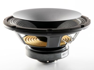
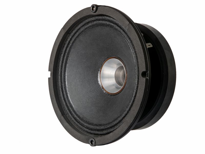
The CX6F-140F is a high efficiency, (93dB 1watt / 1 meter) 6.5-inch coaxial speaker with very linear frequency response characteristics and high power handling capability. The mid-woofer utilizes REDCATT developed paper pulp cone that has proven its performance in many our successful designs. The HF section was designed around our most successful dome assembly as used in 140FCD. The mini waveguide is CNC machined from single piece of aluminum, given the whole assembly incredible precision. The combination of used materials with our state of the art quality production yields in well performing driver even in the most demanding extreme conditions.
Magnetic circuit design
REDCATT engineers have developed ferrite-neodymium based magnetic circuit, capable of delivering the highest level of performance in a small form factor. The combination of ferrite and neodymium delivers an excellent magnetic performance. The magnetic circuit design is optimized to generate the minimum amount of flux modulation, providing exceptional stability. Aluminum demodulation ring is assembled in the HF section.
Specifications
General Specs
Nominal Diameter
6"
Rated Impedance
8 Ohm
Magnet
Hybride
Basket Material
Steel
Power Handling
AES Power
LF: 100 W / HF: 30 W
Continuous Power
LF: 200 W / HF: 60 W
Peak Power
LF: 400 W / HF: 120 W
Voice Coil
Diameter
LF: 44.5 mm / HF: 35.6 mm
Winding Wire
CCAR
Former
Glass Fiber/kapton
Winding Height
10/2.5 mm
T/S Parameters
Qes
0.520
Qms
4.73
Qts
0.470
Vas
4.40 liters
Sd
141.00 cm\u00B2
Mms
10.90 grams
Rms
1.75
Cms
0.1600
Bl
9.27 T\u00B7m
Le
0.450 mH
Sensitivity
95.50 dB
Design Details
Surround Material
fabric/PEN
Cone/Dome Material
Paper CF/PEN
Spider
Nomex
T-Plate
6 mm
Xmax (peak)
2 mm
Xmech
8 mm
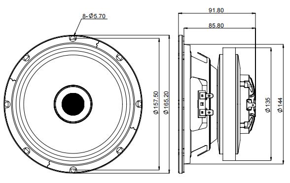
Overall Diameter
165.20 mm
Bolt Circle Diameter
157.50 mm
Baffle Cutout Dia.
144.00 mm
Mounting Holes
8
Depth (flange to rear)
85.80 mm
Net Weight
2.10 kg
Ordering Codes
Product Code
CX6F140FX8X8-361C
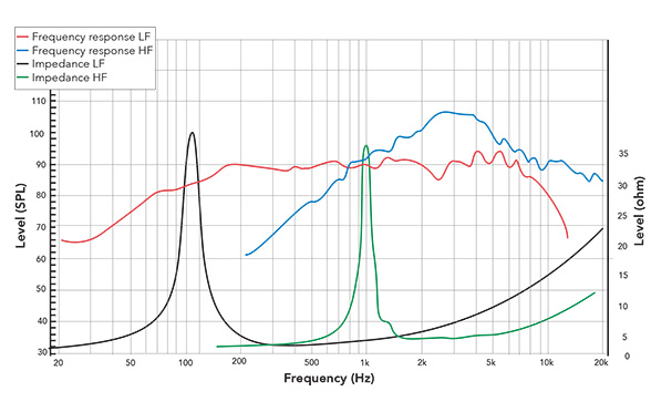
Frequency Response & Impedance
2D Drawing
Enclosure Recommendations
LF enclosure alignments:
  - Vented (primary)  -  50 mm port:
      5 L / Fb = 95 Hz / ~94 mm physical port  / 8.57 m/s peak port velocity
      8 L / Fb = 80 Hz / ~79 mm physical port  / 7.22 m/s peak port velocity
     12 L / Fb = 70 Hz / ~64 mm physical port  / 6.32 m/s peak port velocity
    (All velocities within hi-fi 17 m/s and PA 22 m/s limits; subsonic high-pass
     filter at Fb - 10 Hz mandatory to prevent over-excursion below tuning frequency)
  - Sealed (secondary):
      3.49 L / Qtc = 0.707 / f-3dB = 182 Hz  (Butterworth)
      1.94 L / Qtc = 0.85  / f-3dB = 188 Hz
      1.25 L / Qtc = 1.00  / f-3dB = 203 Hz
      0.80 L / Qtc = 1.20  / f-3dB = 227 Hz  (very compact; sub-assisted applications)
Frequently Asked Questions
- - LF and HF combined magnetic circuit
- - Compact, but powerful speaker
- - Magnetic circuit combining ferrite and neodymium magnets
LF enclosure alignments:
  - Vented (primary)  -  50 mm port:
      5 L / Fb = 95 Hz / ~94 mm physical port  / 8.57 m/s peak port velocity
      8 L / Fb = 80 Hz / ~79 mm physical port  / 7.22 m/s peak port velocity
     12 L / Fb = 70 Hz / ~64 mm physical port  / 6.32 m/s peak port velocity
    (All velocities within hi-fi 17 m/s and PA 22 m/s limits; subsonic high-pass
     filter at Fb - 10 Hz mandatory to prevent over-excursion below tuning frequency)
  - Sealed (secondary):
      3.49 L / Qtc = 0.707 / f-3dB = 182 Hz  (Butterworth)
      1.94 L / Qtc = 0.85  / f-3dB = 188 Hz
      1.25 L / Qtc = 1.00  / f-3dB = 203 Hz
      0.80 L / Qtc = 1.20  / f-3dB = 227 Hz  (very compact; sub-assisted applications)
PA coaxial column / ceiling; pair with active subwoofer
AES Power: LF: 100 W / HF: 30 W,
Continuous: LF: 200 W / HF: 60 W,
Peak: LF: 400 W / HF: 120 W.
Sensitivity: 95.50 dB (1W/1m).